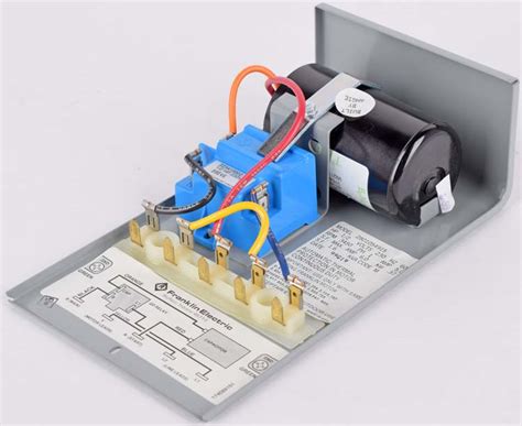
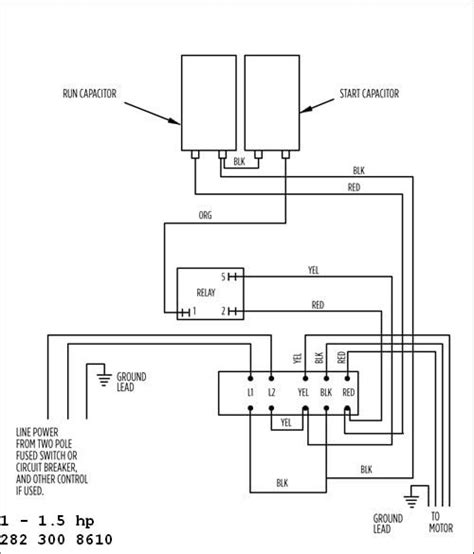
connecting a franklin electric qd control box By following these simple steps, you can easily and quickly wire your Franklin Electric QD Control Box 1 3 HP. By understanding the wiring diagrams and following the best wiring practices, you can ensure that your . Once the hole is cut in the wall for the box, feed the cable (or cables) out through .
0 · qd control box 2801084915
1 · franklin electric submersible motor control
2 · franklin electric control box manual
3 · franklin electric control box capacitor
4 · franklin electric control box 2hp
5 · franklin electric 2823028110 wiring diagram
6 · franklin control box wiring diagram
7 · franklin control box capacitors
Just replace it with a usb outlet. Easy 5 min replacement. depending on the box, you might get a 4x4 one device mud ring and a cover plate and install a usb receptacle. Would something like the following work? https://www.homedepot.com/p/NYCE-Power-2-USB-Port-Lamp-Charger-Adapter-in-White-813194/311212680.
In this video, Chris shows you how to wire the Franklin Electric QD Control Box. All 3-wire submersible pumps from 1/3 up to 1 HP utilize a QD control box to. View these Products: https://www.rcworst.com/Control-Boxes-c341.htmlFranklin Electric AIM Manual: https://www.rcworst.com/Shared/content/mfr/franklin_electri. In today's video, we are going to cover troubleshooting a franklin electric QD submersible well pump control box. We are going to share with you some money saving tips to test your own equipment. By following these simple steps, you can easily and quickly wire your Franklin Electric QD Control Box 1 3 HP. By understanding the wiring diagrams and following the best wiring practices, you can ensure that your .
• Connect the incoming 230V AC Mains supply to the control box as shown in the wiring diagram (Figure A). • Important: Connect the Mains Earth wire to green terminal The Franklin Electric QD Control Box Wiring Diagram includes detailed illustrations and descriptions of the different electrical components and their connections. This diagram .
Franklin Electric QD Control Box Wiring Diagrams provide a comprehensive look at the electrical systems inside the Franklin Electric QD Control Box. These diagrams show the various components of the system, as . QD Boxes are designed for use with 3-wire, single phase submersible motors from ? to 1 hp. Troubleshooting inside the box is made simple by the control components .

QD Pumptec easily plugs into 3-wire Franklin QD Control Boxes with no additional wiring or tools required. QD Pumptec allows the user to choose the standard factory calibration for underload . In this video, Chris shows you how to wire the Franklin Electric QD Control Box. All 3-wire submersible pumps from 1/3 up to 1 HP utilize a QD control box to. View these Products: https://www.rcworst.com/Control-Boxes-c341.htmlFranklin Electric AIM Manual: https://www.rcworst.com/Shared/content/mfr/franklin_electri.
In today's video, we are going to cover troubleshooting a franklin electric QD submersible well pump control box. We are going to share with you some money saving tips to test your own equipment.Franklin Electric submersible control boxes are designed and optimized specifically for Franklin three-wire, single-phase motors rated 1/3 to 15 hp. Quick Disconnect (QD) boxes make trouble shooting simple by automatically disconnecting the control components from . By following these simple steps, you can easily and quickly wire your Franklin Electric QD Control Box 1 3 HP. By understanding the wiring diagrams and following the best wiring practices, you can ensure that your motor runs safely and efficiently.
• Connect the incoming 230V AC Mains supply to the control box as shown in the wiring diagram (Figure A). • Important: Connect the Mains Earth wire to green terminal The Franklin Electric QD Control Box Wiring Diagram includes detailed illustrations and descriptions of the different electrical components and their connections. This diagram also contains helpful tips and warnings on how to avoid electrical hazards.

Franklin Electric QD Control Box Wiring Diagrams provide a comprehensive look at the electrical systems inside the Franklin Electric QD Control Box. These diagrams show the various components of the system, as well as the wiring that connects them all.
QD Boxes are designed for use with 3-wire, single phase submersible motors from ? to 1 hp. Troubleshooting inside the box is made simple by the control components automatically disconnecting from the system when the lid is removed. I have outlined some troubleshooting steps below to help investigate problems with your QD Control Box. Caution!QD Pumptec easily plugs into 3-wire Franklin QD Control Boxes with no additional wiring or tools required. QD Pumptec allows the user to choose the standard factory calibration for underload or to calibrate to a particular system. In this video, Chris shows you how to wire the Franklin Electric QD Control Box. All 3-wire submersible pumps from 1/3 up to 1 HP utilize a QD control box to.
qd control box 2801084915
View these Products: https://www.rcworst.com/Control-Boxes-c341.htmlFranklin Electric AIM Manual: https://www.rcworst.com/Shared/content/mfr/franklin_electri.
In today's video, we are going to cover troubleshooting a franklin electric QD submersible well pump control box. We are going to share with you some money saving tips to test your own equipment.Franklin Electric submersible control boxes are designed and optimized specifically for Franklin three-wire, single-phase motors rated 1/3 to 15 hp. Quick Disconnect (QD) boxes make trouble shooting simple by automatically disconnecting the control components from . By following these simple steps, you can easily and quickly wire your Franklin Electric QD Control Box 1 3 HP. By understanding the wiring diagrams and following the best wiring practices, you can ensure that your motor runs safely and efficiently.
• Connect the incoming 230V AC Mains supply to the control box as shown in the wiring diagram (Figure A). • Important: Connect the Mains Earth wire to green terminal
The Franklin Electric QD Control Box Wiring Diagram includes detailed illustrations and descriptions of the different electrical components and their connections. This diagram also contains helpful tips and warnings on how to avoid electrical hazards. Franklin Electric QD Control Box Wiring Diagrams provide a comprehensive look at the electrical systems inside the Franklin Electric QD Control Box. These diagrams show the various components of the system, as well as the wiring that connects them all. QD Boxes are designed for use with 3-wire, single phase submersible motors from ? to 1 hp. Troubleshooting inside the box is made simple by the control components automatically disconnecting from the system when the lid is removed. I have outlined some troubleshooting steps below to help investigate problems with your QD Control Box. Caution!
franklin electric submersible motor control

$19K+
connecting a franklin electric qd control box|franklin control box capacitors