electric motor junction box position The Motor Too Hot trip indicates a motor thermal overload based on the Rated . This groundbreaking new text connects each welding technique to a useful and creative take-home project, making exercises both practical and personal for students'and avoiding the tedium of.
0 · slang for motor junction box
1 · replacement motor terminal box
2 · motor terminal box catalogue
3 · motor terminal block catalogue
4 · junction box replacement
5 · electrical motor terminal box
6 · 3 phase motor terminal box
7 · 3 phase motor terminal block
Any chemicals that are on in the metal will become mixed with welding fumes, a combination that can be extremely hazardous and/or flammable. why does the metal that has been used before need to be cleaned prior to welding? Areas that have 10,000 cubic ft or more per welder or have the ceiling 16 ft high or higher.
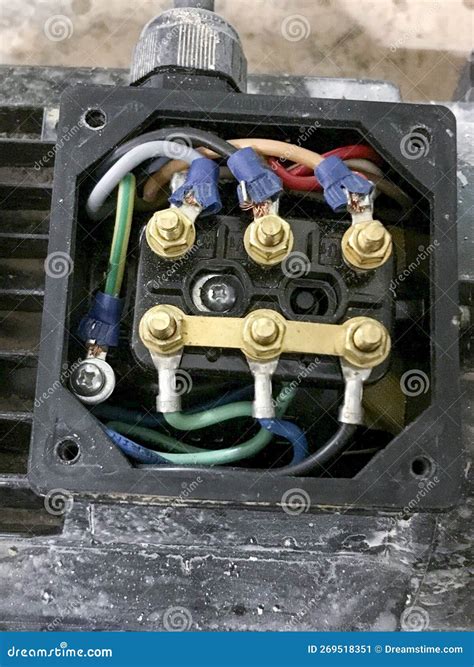
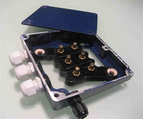
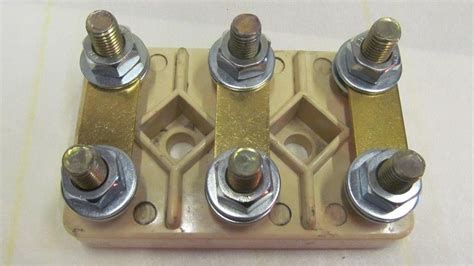
The standard IEC mounting position places the junction box on the top of the motor, known as the IM B3 mounting position in IEC frame (or F3 in NEMA frames). On the other hand, the NEMA standard mounting position is referred to as F1, with the junction/conduit box located on the left .Frame size, Motor Power and Motor current values for a typical 4 pole, 400v motor.Motor thermistor over-temperature: The motor thermistor connected to terminal .
The Motor Too Hot trip indicates a motor thermal overload based on the Rated .
The motor works at a constant load for enough time to reach temperature .For example, an 80°C rise is often referred to as a 'Class B', as 80°C is the .NOTE: For all NEMA mounting configurations, refer to NEMA MG 1-2009.
Fourth, where is the conduit box to be located on the motor frame to best meet the needs of the installation’s wiring arrangement? Two points must be checked: The position of the conduit box on the motor frame. The position of the conduit .In motor mounting position B8 (= M3), T is at the bottom. The position of the cable entry can be selected as well. The positions are "X" (= standard position), "1", "2" or "3" ( → Figure 86). .IEC 60034 Rotating Electrical Machines is specification title. Name two motor mounting types. Who maintains the two global standards for motor construction? What does the D dimension . Download and keep our Electrical Motor Mounting Position Chart. View 12 of the most common Motor Mounting Codes and Positions. Discover what each reference means and Why each Code is important in Designating .
• The position of motor terminal box is determined by looking into the fan guard when the gearmotor is in M1 mounting position. • The position of the terminal box is specified with 0°, .
slang for motor junction box

x: facing down when box is vertical 1: facing towards motor shaft 3: facing away from motor shaft 33: 33° position 123: 123° position 213: 213° position 303: 303° position note: [1] standard .Grasp the motor connectors and gently pull the additional lead wires through the connector holes. Position the cover gasket so that the side with the two larger mounting holes is over the motor .
1966 cutlass sheet metal
Here we will discuss some of these procedures and outline a few of the advantages and disadvantages of each. We will not consider the starting method or internal connection of the motor, but only the methods used to connect the .The standard IEC mounting position places the junction box on the top of the motor, known as the IM B3 mounting position in IEC frame (or F3 in NEMA frames). On the other hand, the NEMA standard mounting position is referred to as F1, with the junction/conduit box located on the left side of the motor facing the output shaft.NOTE: For all NEMA mounting configurations, refer to NEMA MG 1-2009.
Fourth, where is the conduit box to be located on the motor frame to best meet the needs of the installation’s wiring arrangement? Two points must be checked: The position of the conduit box on the motor frame. The position of the conduit opening.In motor mounting position B8 (= M3), T is at the bottom. The position of the cable entry can be selected as well. The positions are "X" (= standard position), "1", "2" or "3" ( → Figure 86). Unless indicated otherwise, you will receive the terminal box type 0° (R) with cable entry "X".IEC 60034 Rotating Electrical Machines is specification title. Name two motor mounting types. Who maintains the two global standards for motor construction? What does the D dimension specify?
replacement motor terminal box
Download and keep our Electrical Motor Mounting Position Chart. View 12 of the most common Motor Mounting Codes and Positions. Discover what each reference means and Why each Code is important in Designating Motor Type.• The position of motor terminal box is determined by looking into the fan guard when the gearmotor is in M1 mounting position. • The position of the terminal box is specified with 0°, 90°, 180° or 270°, as shown in the figure below. • For mounting positions other than M1, the terminal box positions rotate with the feet of gear unit.
x: facing down when box is vertical 1: facing towards motor shaft 3: facing away from motor shaft 33: 33° position 123: 123° position 213: 213° position 303: 303° position note: [1] standard (typical) configuration: fm-3-3-213 [2] drain hole (if present) at 6 o'clock sample model code [a] mounting configuration [b] junction box position [c .Grasp the motor connectors and gently pull the additional lead wires through the connector holes. Position the cover gasket so that the side with the two larger mounting holes is over the motor power connector. Slide the connectors through the connector hole(s) in the cover gasket.
Here we will discuss some of these procedures and outline a few of the advantages and disadvantages of each. We will not consider the starting method or internal connection of the motor, but only the methods used to connect the motor leads to incoming power. Topics covered include: Types of terminations; Insulating the joints; Medium voltage .
The standard IEC mounting position places the junction box on the top of the motor, known as the IM B3 mounting position in IEC frame (or F3 in NEMA frames). On the other hand, the NEMA standard mounting position is referred to as F1, with the junction/conduit box located on the left side of the motor facing the output shaft.NOTE: For all NEMA mounting configurations, refer to NEMA MG 1-2009.

Fourth, where is the conduit box to be located on the motor frame to best meet the needs of the installation’s wiring arrangement? Two points must be checked: The position of the conduit box on the motor frame. The position of the conduit opening.In motor mounting position B8 (= M3), T is at the bottom. The position of the cable entry can be selected as well. The positions are "X" (= standard position), "1", "2" or "3" ( → Figure 86). Unless indicated otherwise, you will receive the terminal box type 0° (R) with cable entry "X".
IEC 60034 Rotating Electrical Machines is specification title. Name two motor mounting types. Who maintains the two global standards for motor construction? What does the D dimension specify?
motor terminal box catalogue

Download and keep our Electrical Motor Mounting Position Chart. View 12 of the most common Motor Mounting Codes and Positions. Discover what each reference means and Why each Code is important in Designating Motor Type.• The position of motor terminal box is determined by looking into the fan guard when the gearmotor is in M1 mounting position. • The position of the terminal box is specified with 0°, 90°, 180° or 270°, as shown in the figure below. • For mounting positions other than M1, the terminal box positions rotate with the feet of gear unit.

x: facing down when box is vertical 1: facing towards motor shaft 3: facing away from motor shaft 33: 33° position 123: 123° position 213: 213° position 303: 303° position note: [1] standard (typical) configuration: fm-3-3-213 [2] drain hole (if present) at 6 o'clock sample model code [a] mounting configuration [b] junction box position [c .Grasp the motor connectors and gently pull the additional lead wires through the connector holes. Position the cover gasket so that the side with the two larger mounting holes is over the motor power connector. Slide the connectors through the connector hole(s) in the cover gasket.
1969 camaro sheet metal
1968 camaro junction box
Aluminum and stainless steel garage cabinets are the best options for a busy workshop, with a heavy, durable design that can hold all your tools while withstanding the .
electric motor junction box position|replacement motor terminal box